Have you heard of Young's experiment? It is a phenomenon where interference fringes are formed due to the interference of waves passing through two slits. Let's observe Young's experiment through a graph!
Animation
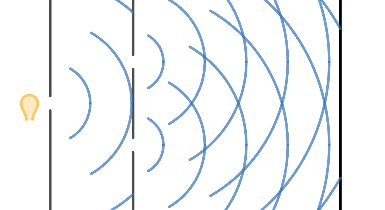
Light emitted from the light source on the left passes through the two slits in the middle. The two lights passing through the slits interfere with each other, and as a result, interference fringes are projected onto the screen on the right.
Let's take a closer look!
The Mechanism of Young's Experiment
① Passing through the first slit
First, the light emitted from the light source passes through the first slit.

This first slit exists to align the phase of the waves emitted irregularly from the light source.
The important point is that the wave passing through the slit undergoes diffraction. In other words, after passing through the slit, the wave does not proceed straight ahead but spreads out around the gap.

② Passing through the two slits
Next, this wave passes through the two slits.

Of course, as before, these waves also undergo diffraction.
Since the phase was aligned at the first slit, the phases at the two slits are equal. In other words, the waves spread out from the two slits in exactly the same way.
Formation of interference fringes
The waves passing through the two slits interfere with each other. Points where the waves reinforce each other are projected as bright lines, and points where they cancel each other out are projected as dark lines, creating interference fringes.

Spacing of Interference Fringes
Let's calculate the spacing of the interference fringes!
Imagine the diffracted light traveling at an angle . The question is: do these waves reinforce each other?

In other words, do the two light waves shown in the figure reinforce each other?
To find the path difference between these two waves, we could use the Pythagorean theorem for precise calculations. However, for simplicity, let's use a geometric approximation.
Assume the screen is far enough away compared to the slit spacing and wavelength. In other words, let's assume .
Since the screen is very far away, the two light waves passing through the slits can be considered nearly parallel. Here's the situation:

Thus, the path difference is represented by the red part in the figure.

Therefore, if the path difference is , then:
Also, from the first figure:
Since and , we can approximate , so:
This is how the path difference is determined! Therefore, the condition for these lights to reinforce each other is, given the wavelength of light ,
Here, is any integer. Thus, the spacing of the bright lines is:
And that's how it's calculated!