
Have you ever noticed the fascinating patterns created when two water surface waves interfere? Let's explore the interference of water surface waves through an engaging animation!
Animation
Antinodal Line | Nodal Line |
|---|---|
By default, the composite wave (the observable wave resulting from interference) is displayed. To start, turn off the "Composite Wave" switch and turn on the "Wave 1" switch.
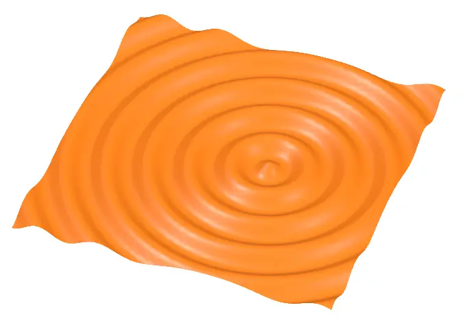
You should now see an orange water surface wave, as shown in the image above. Next, turn off the "Wave 1" switch and turn on the "Wave 2" switch.
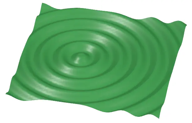
This will display a green water surface wave with its center (wave source) shifted, as shown in the image.
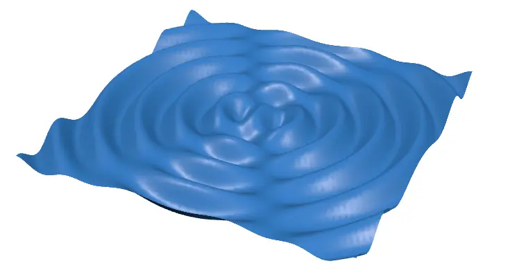
The wave resulting from the interference (or superposition) of these two waves is the composite wave that was initially displayed. Let's analyze this composite wave together! (We'll explain the concepts of antinodal and nodal lines later.)
Characteristics of the Composite Wave
Let's dive into the characteristics of the composite wave! Broadly speaking, you can observe the following features:
Characteristics of Water Surface Wave Interference
- Lines connecting points of maximum amplitude are called antinodal lines.
- Lines connecting points of zero amplitude are called nodal lines.
- When the wave sources are out of phase, the antinodal and nodal lines switch roles.
What are Antinodal and Nodal Lines?
When water surface waves overlap, points of maximum amplitude and points of zero amplitude form distinct lines. These are known as antinodal lines and nodal lines, respectively.
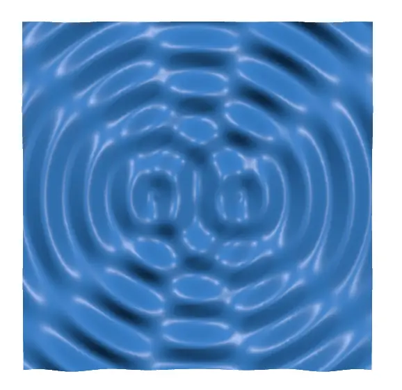
Take a look at the top view of the composite wave below. Can you spot any lines?
By turning on the "Antinodal and Nodal Lines" switch, you can visualize these lines. They appear as follows:
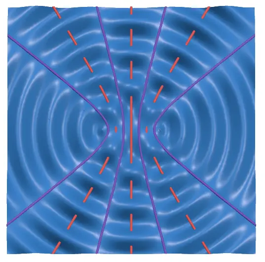
The red lines represent antinodal lines, while the purple lines represent nodal lines.
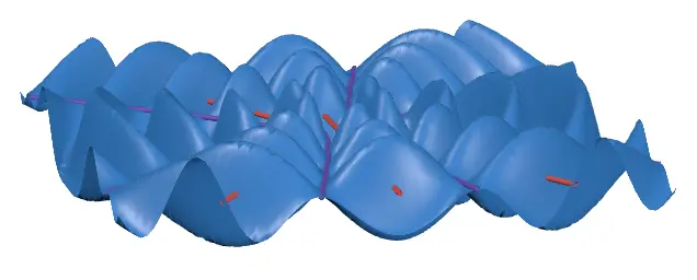
By increasing the amplitude and observing from the side, you can clearly see that points on the antinodal lines have maximum amplitude, while points on the nodal lines have zero amplitude.
This represents the case where the wave sources are in phase, meaning the two wave sources vibrate in sync.
Now, turn on the "Out of Phase" switch. The two wave sources will start vibrating in opposite directions.
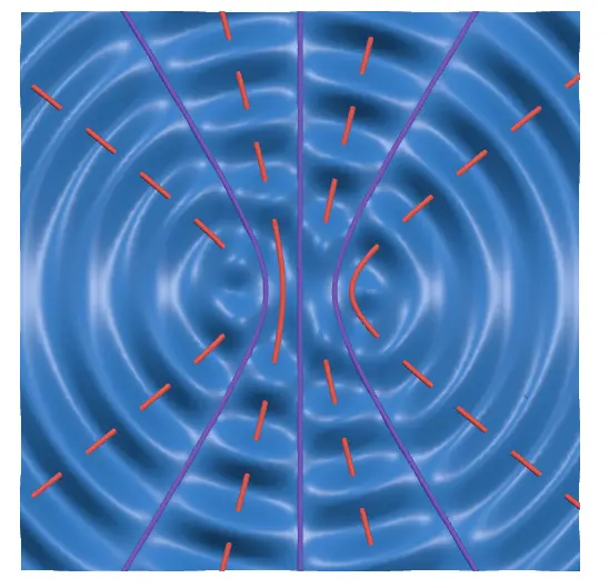
As shown in the image, the antinodal and nodal lines are reversed.
Positions of Antinodal and Nodal Lines
Whether a point has maximum amplitude (antinodal) or zero amplitude (nodal) depends on the distances from the point to the wave sources. The difference in these distances is called the path difference.
Wave Interference
Let the path difference be , the wavelength be , and be any integer. Then:
【When the wave sources are in phase】
- → Antinode
- → Node
【When the wave sources are out of phase】
- → Antinode
- → Node
This principle applies not only to water surface waves but also to the interference of any type of waves.
By considering the path difference, you can determine the positions of the antinodal and nodal lines.
Let the positions of the wave sources be . Then, the path difference at a point is:
Using this formula and the concepts discussed earlier, you can derive the specific equations for the antinodal and nodal lines. However, these equations are complex and will be omitted here.
Nevertheless, it's easy to see that the antinodal and nodal lines form hyperbolas.
These lines connect points with a constant path difference, meaning they connect points where the difference in distances from the wave sources is constant.
This is the definition of a hyperbola! (In some cases, they can also appear as straight lines.)

